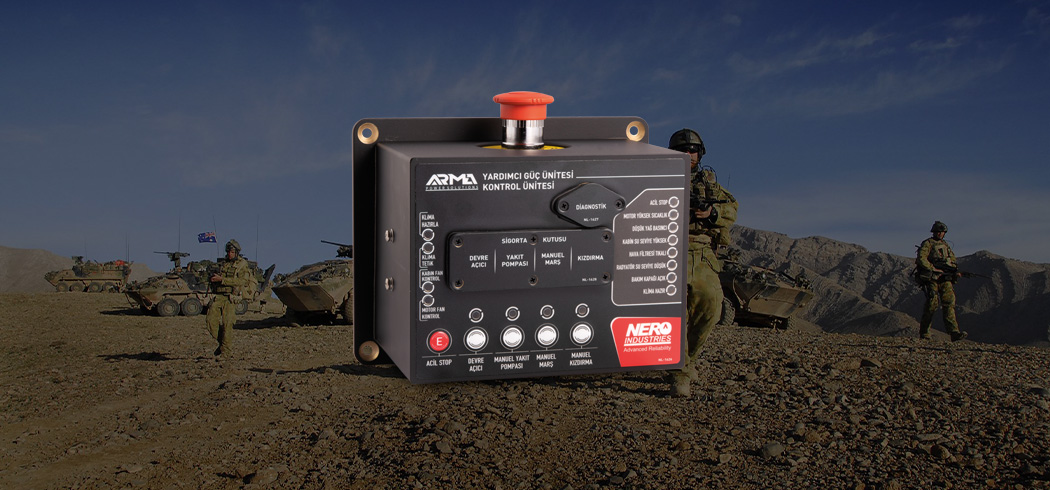
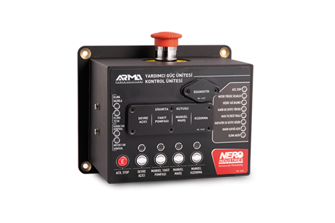
1. A/C CLUTCH: The air conditioning system cannot be started while the corresponding LED is on.
2. HYDRAULIC SOLENOID: The corresponding LED light comes on when the hydraulic solenoid is activated.
3. HYDRAULIC FAN PWM : Hydraulic LED speed decreases as the fan speed increases.
4. RADIATOR FAN PWM : The corresponding LED light level decreases while radiator fan speed increases.
5. EMERGENCY STOP : The corresponding LED lights if any of the emergency stop buttons are active.
6. HIGH ENGINE COOLANT TEMP : The corresponding LED lights when the engine water temperature is high.
7. LOW OIL PRESSURE: The corresponding LED lights when the engine oil pressure is low.
8. HIGH CABIN WATER LEVEL: The corresponding LED lights when there is no water in the cab. If there is water, it goes out.
9. AIR FILTER CLOGGING: The corresponding LED is lights if the air filter is clogged.
10. LOW RADIATOR WATER LEVEL : The corresponding LED lights when there is no water in the radiator. If there is water, it goes out.
11. FSS ALARM: The corresponding LED is lights when the event of an alarm in the APU engine compartment.
12. WATER IN FUEL FILTER: The corresponding LED lights when the water level in the fuel water filter increases.